|
LiFe Receiver Batteries for SPA
Airplanes
Part 3 - Building Charge and Test Cables
Jim Johns
Links to other articles in this series:
Part 1 - Why Change
to LiFe Batteries
Part 2 -
Battery Pack and Switch Modifications
If you've decided to try onboard
balance charging, you'll need cable to properly charge and
check your LiFe receiver pack. One nice thing about this
type of charging - you can just add servo extensions as
needed to reach from charger to airplane.
|
Building the Test Cable
|
|
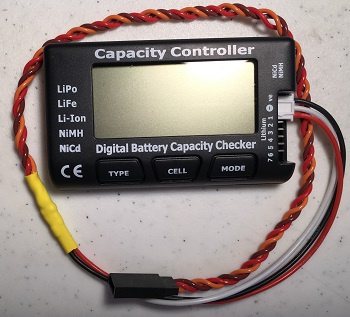
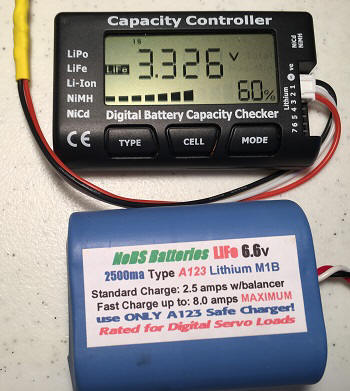
This is my
completed test cable plugged into my battery
checker. Notice that it's connected with the black
wire going to ground. |
 |
|
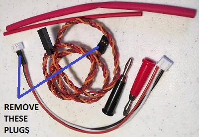
There are only 3 things needed to build this test
cable.
- Servo extension of your choice. I prefer 22
AWG (HD) 12" (300mm) extensions.
- This is a JR style extension, so the
Brown wire is negative, the Red wire
Positive, and the Orange wire is Signal.
- These would be Black, Red, and White
respectively on a Futaba style extension.
- JST-XH 2S Balance Extension.
Note the 3 wires - Black, White and Red.
- Two sizes of heat shrink tubing.
|
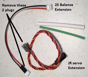 |
First thing to do is to
prepare the wires. Cut off the connectors mentioned
above and
strip the wires. Slip short pieces of smaller
diameter heat shrink tubing (green) over each wire,
along with a longer piece of the larger diameter
heat shrink over all three wires to strengthen the
connection.
Connect the wires
as follows.
JST-XH 2S Extension
(left side) |
Servo Extension
(right side) |
|
Black (Pin 0 - ground) |
Black (Battery -) |
|
White (Pin 1, between the 2 cells) |
Orange (Signal) |
|
Red (Pin 2, both cells) |
Red (Battery +) |
The photo shows the three steps of
connecting the wires.
- The center pair is twisted together.
- The top pair has been soldered.
- The bottom pair has had the heat shrink
tubing slid over the soldered joint and shrunk
using a Monokote Heat Gun.
|
 |
| This is a close up of the
finished connections. Please use longer pieces of
heat shrink tubing if you need. I've been doing this
for a long time and tend to use the smallest pieces
I can get away with. |
 |
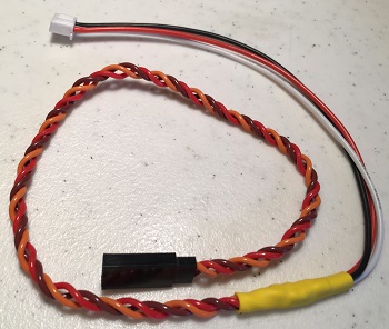
| This is the completed
cable. I decided to use yellow heat shrink to
strengthen the connection because it was slightly
larger diameter than the white. |
 |
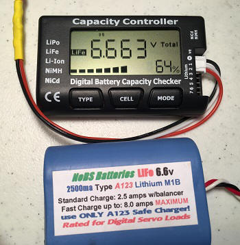
Time to see if it works.
Notice how the cable is connected to the battery
checker.
I'm checking one of my A123 LiFe packs that
is at storage charge voltage.
This photo shows the total voltage of both cells. |
 |
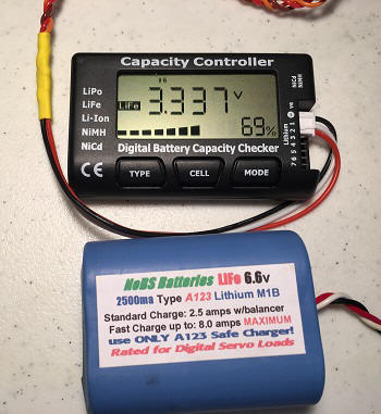
| This photo shows the
voltage of only Cell 1, which is connected directly
to the BLACK (negative) wire of the
pack. Notice the small "1S" at the top above and to
the left of the first 3 in the voltage display. |
 |
| This photo shows the
voltage of only Cell 2, which is connected directly
to the RED
(positive) wire of the pack. Notice the small "2S"
at the top above the decimal point in the voltage
display. |
 |
|
Building the Charging Cable
WARNING: Maximum
allowable charging current
is about
3 AMPS due to
wiring limitations!
|
|
Here are the parts you'll need if you've decided
to build your own charge cable.
- A pair of banana plugs
- A JST-XH 2S balance extension
- A servo extension to match your radio.
A generic is fine as long as it fits your charge
switch. I like to use a 24" long, 22AWG (HD)
extension. It can easily be lengthened if needed by adding
additional servo extensions.
NOTE:
Aftermarket charge switches and servo extensions
come in at least three distinctly different varieties,
so be sure to use one that works with your
setup.
- JR style - This type has plugs on both ends
that are compatible with JR and Hitec radios.
- Futaba style - These have plugs with the
blades Futaba uses for orientation on both ends.
- Hybrid or Universal style - These have a JR
male connector (receiver end) which will plug
into almost any brand receiver and a Futaba female
connector (servo end) that virtually any brand
servo will plug into. These can be used as servo
extensions on virtually any radio system, but
the female connector may be physically too wide to
plug into some charge switches.
|
 |
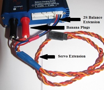
This is one of my charging cables shown plugged into
my SkyRC IMAX B6 charger. Use the techniques from
above to build this cable as well.
The RED
and BLACK wires from the 2S balance
extension and the
RED and BROWN
wires from the servo extension are attached to the
appropriate banana plugs. Some banana plugs work
simply by screwing the colored cap onto the metal
plug to capture and hold the wires, while other
require soldering. The choice is up to you.The
center wire from the balance extension -
BLUE
in this case - is then soldered to the signal wire
of the servo extension -
ORANGE on this JR extension.
This solder joint is covered by the small white heat
shrink tubing hiding inside the larger blue shrink tubing
that stabilizes and strengthens the cable. The small
red heat shrink tubing simply keeps the wires
together neatly.
Note: The signal wire shown here is orange and
the Negative wire is brown because this is a JR
style extension. They would be white and black
respectively on the Futaba style extension.
|
 |
|