|
LiFe Receiver Batteries for SPA
Airplanes
Part 2 -
Modifying the Charge Switch and Generic
LiFe Battery
Pack
for in-Plane Balance Charging and Checking
Jim Johns
Links to other articles in this series:
Part 1 - Why
change to LiFe Receiver Batteries
Part 3 -
Building Charge and Test Cables
OK, so you've decided to try a LiFe
receiver conversion, but don't want to spend a bunch of
money on A123 pack until you're sure you want to commit to
this technology. Below I'll show you a simple way to modify
any generic LiFe receiver battery pack to allow onboard
balance charging and checking.
|
Modifying Your 3-Wire Charge Switch
|
|
If you plan to balance charge in your airplane,
you'll need a 3-wire charge switch. Some aftermarket
models only use two wires which won't work for this
application - you need 3 wires. You'll either need to
modify your own switch or purchase one. NoBS
Batteries and Electrodymanics sell
both the modified switch and the charge
cable if you'd rather go that way.
If you decide to build your own, go to this
webpage - http://hangtimes.com/a123rxsetup.html - and scroll down to this article
*Basic Combo Switch for Single Lead Balance
Charging. It will show you exactly how to modify your existing
3-wire switch. This shouldn't take more than 5
minutes, as getting at the connector plugged into
the receiver will be the hardest part if it's mounted in the
plane. Just lift up the plastic tongue holding the
signal lead - ORANGE on JR or WHITE on Futaba - and
pull out that wire. Fold it back and insulate it
with electrical tape or heat shrink tubing as shown.
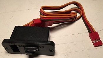
Here's on of my switches for reference.
- The upper photo shows an unmodified ED Ultra II
Charge Switch I bought at Perry in 2015.
- The lower photo shows just the lead that plugs
into the receiver of the same switch before and after
modification. The stock configuration is on the left
and the modified switch
with the signal wire removed from the connector,
folded back on itself and covered with heat shrink tubing
is on the right.
Sources:
Here's the standard charge switch if you want to make
your own:
http://www.electrodynam.com/rc/usw/index.shtml
If you'd rather not make your own, here are two
places you can purchase them.
NOTE: ED usually has a booth at the Perry, GA Southeastern
Model Show in March and prices are lower there than
shown on the website.
|

|
|
Modifying a Generic LiFe Battery Pack
|
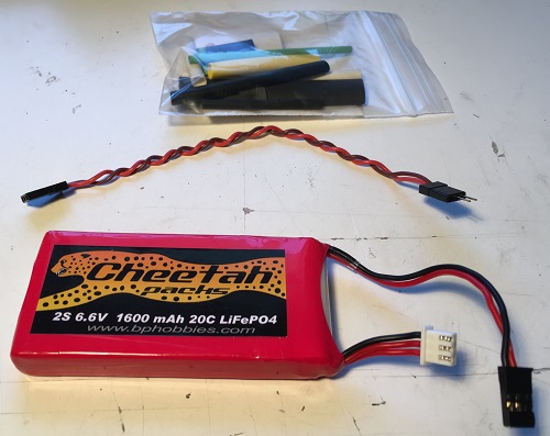
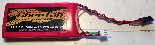
| Let's modify a generic 2S
LiFe receiver pack, such as the 1600 mah Cheetah pack shown
here, to allow balance charging and testing of
each cell through the charge
switch. These are the supplies you'll need.
- LiFe receiver battery pack.
- 6" servo extension - style or brand doesn't
matter.
- Heat shrink tubing.
|
 |
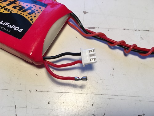
Here I've removed one wire
from the male end of the servo extension which is the end that would plug into your receiver.
Refer to the section called "*Basic Combo Solution
Switch Mod for Single Lead Balance Charging" on the
web link below to see how to remove this wire from the
connector.
http://hangtimes.com/a123rxsetup.html.
Separate this wire from the rest of the extension
- untwist it in this case - and clip it off as close as possible to the other
connector. |
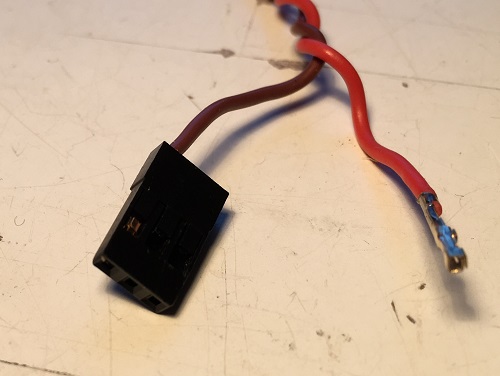 |
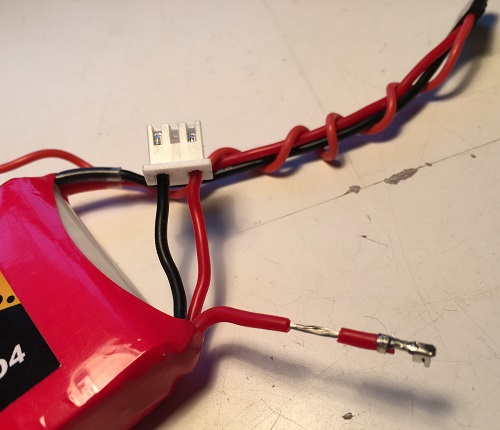
| This is a close up of the
connector end of the wire. Each side is different,
so notice the configuration. |
 |
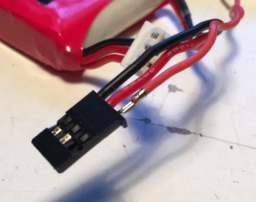
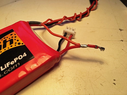
| Here's the additional wire
being inserted into the battery pack connector. Note
that the top side shown in the photo immediately above is
UP in this photo. The wire won't
lock into the connector
properly if it isn't. Press it
all the way in until it clicks. Give it a gentle tug
to be sure it's secure. If not, repeat until it is. |
 |
|
You can see the added twisted around the original
red and black wires at the top of this photo.
I've removed the CENTER
connector of the small white JST XH balance plug. This is a
little more difficult than removing the wire from
the servo extension because you have to PRESS DOWN
on the pin itself to be able to remove it from the
plug. The ONLY reason for doing this is to allow me
to put heat shrink tubing around the wire for
insulation. You can skip this step if you'd rather
not tackle it and use electrical tape. It won't be
as pretty, but it will work fine.Regardless of
color, the center wire of this balance plug is
always connected between the two cells of a 2S pack.
This allows for balance charging and measuring each
individual cell of the pack.
|
 |
|
I've stripped back the insulation just a bit to
expose the bare wire. |
 |
|
The added wire is stripped, wrapped around the balance wire and soldered. Cover
with a piece of heat shrink tubing, shrink it, then
reinstall the connector into the plug. Be cautious
of orientation or it won't lock in place. |
 |
|
Here's the completed pack after modification. Notice
the green heat shrink tubing over the solder joint.
This pack is going into my psychodelic green, pink
and black Daddy Rabbit. |
 |
|
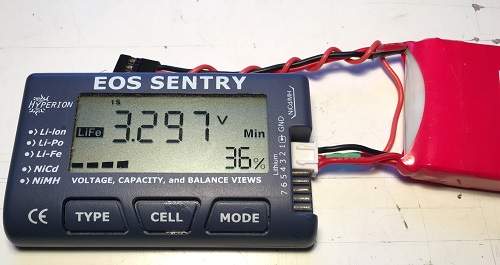
Time for the acid test - does it work or not. This
is how you'd normally check a LiFe battery, with the
JST XH balance plug connected to my battery
checker. The meter is reading the voltage of the
first cell connected to the negative lead of the
pack - note the small "1S" just above the 3 in the
voltage.
Note that the voltage is ~3.3V which is the
nominal storage voltage for LiFe batteries whne not
in use.
|
 |
|
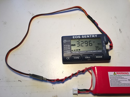
Now to see if our mod worked. Here the battery
checker is connected to the receiver output of the
battery pack which will be connected to the charge
switch. The meter shows the voltage of the
second cell only - the one directly connected to the
red lead - note the small "2S" just above the 3 in
the voltage. |
 |
|